This might end up being a multi-part post. It's my learning journey of fails and little delights (or bigger if I'm successful) on learning about generating art via Processing from data obtained from the accelerometer from the Circuit Playground Express.
- Components mentioned in this project
- Software references
- Processing
- PyProcessing
- Circuit Python
- Arduino
- VNC Viewer - Virtual Network computing
Day 1 PyProcessing, Circuit Python, E-ink Gizmo - lots of experimenting
Ok, what I wanted to do (which made sense in my head) was to create an image with Processing when it detects sensor changes in CPX.
I was thinking of going whole hog with Python as there's a Python library for Processing via py.processing.org but first off I need to get Processing installed on my Raspberry Pi (model 4 on pi-top[4]). I quickly realised the normally version via Processing site doesn't work, but there's a pi.processing.org that has a version of Processing specific for it.
Hit download and untarred it and voila, it worked.
Spent some time going through the tutorials with Python on Processing. That was fun... now I want to get cracking on how to get it working with CPX.
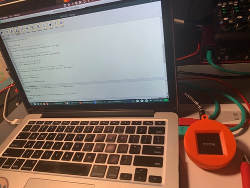
I can get Circuit Python to print to the E-ink Gizmo screen with the text Testing. That's a good start. 😊
Was looking at using command line to call it programmatically... not so straight forward because it specifically needs a really old version of Java... and it doesn't support OpenJDK and just ugh...
Anyway, maybe it wouldn't be so bad to play with Processing, it's only Java light, right. I found that it does interact with GPIO on the Raspberry Pi, so that's a positive.
But I want it to work with CPX. I'll be connecting it with a microUSB cable to the Raspberry Pi (which I'm VNC'd into). So playing with GPIO is a moot point.
Ok, there's too many moving parts here that don't necessarily talk to each other, let's roll back a little. What comes out of the box with Python that can generate images? It's Python Turtle. I kind of ignored it as I was teaching kids about Python with it late last year, but I do notice a lot of people create generative art with Python Turtle.
The next question is how to save the output of Python Turtle.
I can see that you can generate something simple, save it to an image (note, I had to install pillow to use PIL), and also close the Python Turtle window after it generates the image.
So it's back to Circuit Python after all that. Interesting exercise though.
Ok, back to basics
CPX with E-ink Gizmo -> pi-top[4] with Raspberry Pi Model 4
Adafruit Libaries:
- adafruit_display_text
- adafruit_gizmo
- adafruit_il0373.mpy
Group Full RunTimeError for label.py: text was too long
ℹ️ https://github.com/adafruit/Adafruit_CircuitPython_Display_Text/issues/11
Also realising waiting 180s is very boring!
Day 2 Enough with e-ink, let's try TFT Gizmo
Decided to switch to TFT Gizmo - e-ink Gizmo is very slow to work with. It's all ready and set up, and passed the TFT Gizmo test.So finding out how to talk to TFT Gizmo on CPX with Circuit Python.

Modified code so it loads up a bitmap on the TFT Gizmo.

Back to the Processing on the Pi.
Running it via command line (it's warn it's not fully supported on newer versions of Java or OpenJDK).
Created the Python script from the Processing sketch sample. Got the processing-py.jar file.
java -jar processing-py.jar [name of my python script]
It worked!
I wanted to save the image to the disk - used save(), and that worked.
Next I want the dialog to close after it ran - used exit(), and that worked also.
Next thing now is to pop that image onto the TFT Gizmo.
Loaded up the code from the e-ink Gizmo (will be modifying for TFT Gizmo) and its having problem not finding displayio module. Looks like I need to flash it with cpx with displayio (after a bit of troubleshooting).
Then it needed also adafruit_pypixelbuf module.
Ok, now I can modify to look for tft calls nows instead of e-ink.
Moments later, I hit a problem... The dreaded memory allocation errors.
I forgot the flash memory for CPX is quite small.
I've removed comments and imports not needed. I'm only testing the example and can only display 1 of the 3 parts of the code
📍 In case I need to reduce size of my jpg image: https://stackoverflow.com/questions/59483536/why-does-pil-pillow-image-save-reduce-file-size
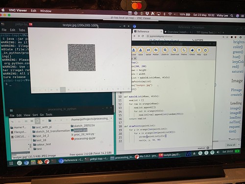
Ok, I just want to bare minimum load an image I generated earlier with Processing, it's a JPG. It gave an error saying it doesn't not support the file format, so I converted it to BMP with PIL.
And tried to load it again, and it worked.
NOTE: READ THE TOP "GREEN BANNER" ABOUT MEM CONSTRAINTS ON https://learn.adafruit.com/adafruit-tft-gizmo/circuitpython-displayio-quickstart 😅 (Thanks to Mick for finding this https://github.com/adafruit/Adafruit_CircuitPython_ST7789/issues/9)
🍷 BREAK 🍷
Day 3 Getting and saving accelerometer data
Ok, today's task is to get value of accelerometer and save to filesystem on CPX. So I tried, and it bounced backOSError: [Errno 30] Read-only filesystem
...hmm, ok-aay.
After a bit of searching I found the solution to write to the filesystem with CircuitPython from an Adafruit article. 🙌
So I created the boot.py, restarted CPX, and yip, the csv was created when the programme started to run.
And as expected from reading the article, when I modified the code, it didn't let me save it.
Workaround is rename boot.py via the Python REPL because you can't edit boot.py. And that worked, I made a quick edit on the code (output 3 readings instead of 10) and saved it!
Renamed the boot file back to boot.py, and hit the reset button on CPX.
Checked the CSV file and it has 3 readings saved to it! Amazing!
Was showing Mick and suggested an alternative as this way may damage the filesystem, and it is pretty hacky. We tried to look at ways to transmit the data over USB serial... bar bringing a wire from one of the pins. Plus we tried switching off the terminal window which replaces the bitmap image on the TFT if we don't use a while loop, again, no easy way to not have the terminal replace the bitmap image.
🧐 I think we have hit the limit of what Circuit Python can do. So onwards to Arduio and see what fun things I can do with that.
Day 4 Arduino time
Moved development onto my Mac from Raspbery Pi.Step 1: Downloaded Arduino on my Mac.
Step 2: ...
Step 3: Profit! 😆
Note that the last time I used this was a number of years ago when I ran a wearable workshop and I was more or less following someone's lead.
Followed instructions from installing libraries right up to testing TFT Gizmo sample code.
Tried to run example code, it failed saying it can't find SP1 library.
At the moment in time, Mick was just passing by and seeing how I got on, and he had more experience in Arduino. He asked if I installed everything. He thinks the board is missing, and suggested to look up setup for CPX for Arduino.
Followed the instructions and ran the blink example. Still didn't work.
The board was still not found, checked the port and changed it, and the blink code works!
Tried the TFT Gizmo example and it didn't work. Re-checked libraries from docs several times, restarted CPX, and even commented out calls to functions to see what works and printing text to serial. Nothing written out to TFT. I do notice the TFT backlight coming on.
Dropped the TFT Gizmo UF2 onto CPX and the test does work.
☕️ BREAK ☕️
Still figuring out why the TFT library not working.
I also wanted to find out how to call the accelerometer via Arduino.
Mick popped up again to see how I was getting on, from his experience of using Arduino, he was asking if maybe when CPX was connecting was not ready yet, so looked up info about Serial on Arduino docs and found:
Added the while loop from the following snippet:
void setup() {
  //Initialize serial and wait for port to open:
  Serial.begin(9600);
  while (!Serial) {
    ; // wait for serial port to connect. Needed for native USB
  }
}

void loop() {
  //proceed normally
}
And the calls in setup() seem to work now. So that's a good sign. Well, the printing to serial. I still haven't got the TFT libraries to work.
I was ignoring this part of the code:
// OPTION 1 (recommended) is to use the HARDWARE SPI pins, which are unique
// to each board and not reassignable.
Adafruit_ST7735 tft = Adafruit_ST7735(TFT_CS, TFT_DC, TFT_RST);

// OPTION 2 lets you interface the display using ANY TWO or THREE PINS,
// tradeoff being that performance is not as fast as hardware SPI above.
//#define TFT_MOSI 29  // Data out
//#define TFT_SCLK 30  // Clock out
//Adafruit_ST7735 tft = Adafruit_ST7735(TFT_CS, TFT_DC, TFT_MOSI, TFT_SCLK, TFT_RST);
Option 2 was recommended for Circuit Playground Classic, so I let it as is. Mick was also looking into it on his laptop and found that using Option 2 works (after we confirmed that our board is CPX). So I used the code from Option 2 and, it works. I don't mind if it's a little slower, I'm just pulling accelerometer data and displaying a generated image as the accelerometer numbers change. Let's pin generating image and displaying it on TFT for now.
So the tft library works at set up. Let's try, say, print X value from the accelerometer in the loop. It failed because of course you can't print a float as text. You have to convert it. And I found many answers following but less so on what library to include including the library to include:
dtostrf(FLOAT,WIDTH, PRECISION,BUFFER);
After a couple of false leads (no surprisingly), this was the library to include for dtostrf to work:
<avr/dtostrf.h>
And that worked. So I called it a night.
Day 5 CPX, Gizmo TFT
Hmm, running Circuit Playground library stops me using the tft library. Had a sounding out with Mick and came to same conclusion to bypass Circuit Python, he said they wrapped it around code for the accelerometer anyway.So went looking at the Circuit Playground source code on github:
- https://github.com/adafruit/Adafruit_CircuitPlayground/blob/master/Adafruit_CircuitPlayground.cpp
- https://github.com/adafruit/Adafruit_CircuitPlayground/blob/master/Adafruit_Circuit_Playground.h
I noticed in the header file it included Adafruit_CPlay_LIS3DH.h, so I commented looked for examples that use LIS3DH libraries, and thankfully there were a few out there, so I added
#include <Adafruit_LIS3DH.h>
#include <Adafruit_Sensor.h>
plus the following declarations
// Used for software SPI
#define LIS3DH_CLK 13
#define LIS3DH_MISO 12
#define LIS3DH_MOSI 11
// Used for hardware & software SPI
#define LIS3DH_CS 10

// software SPI
//Adafruit_LIS3DH lis = Adafruit_LIS3DH(LIS3DH_CS, LIS3DH_MOSI, LIS3DH_MISO, LIS3DH_CLK);
// hardware SPI
//Adafruit_LIS3DH lis = Adafruit_LIS3DH(LIS3DH_CS);
// I2C
Adafruit_LIS3DH lis = Adafruit_LIS3DH(&Wire1);
Not sure if the additional code worked for LIS3DH, so I found the following snippet to check if it was found or not:
if (! lis.begin(0x19)) {   // change this to 0x19 from 0x18 for alternative 	i2c address
	Serial.println("Couldnt start");
	while (1) yield();
}
Serial.println("LIS3DH found!");
And that's where I got stuck... no matter what iterations of commenting out and in I did, or change the i2C address, it came back with
"Couldnt start"
😫 This was head-wrecking for most of the day.
Later that evening
Still having problems getting to connect with the accelerometer. I needed another pair of eyes... well, in truth, I wasn't going to turn in for bed (t was getting really late) as I was being stubborn on trying to figure this out. So Mick took a look as well, and spotted the CPP file I had open in the "begin" function to see how they declared it. Now this was staring in my face the whole time
lis = Adafruit_CPlay_LIS3DH(&Wire1);
Why didn't I try putting &Wire1 as an argument?! 😳
Added the argument, saved and compiled. Hit that upload button, held breath when no errors appeared and.... IT WORKED!
Sample Output from Accelerometer
X:  608  	Y:  5344  	Z:  -15376
Screen should be blue now!
X:  592  	Y:  5296  	Z:  -15584
Screen should be blue now!
X:  752  	Y:  5248  	Z:  -15456
Screen should be blue now!
X:  512  	Y:  5184  	Z:  -15424
Screen should be blue now!
X:  608  	Y:  5200  	Z:  -15488
💤 Bedtime! #KThxBai
Day 6 This blog post, processing
Ok, before I dropped off to sleep, I found the following article which is pretty much what I need to connect arduino to processing and have them sending data between them.- board -> processing : data from accelerometer
- processing -> board : bitmap image generated from accelerometer data
So that's today's goal, at least get processing picking up data from accelerator.
Before that happens, a little side-track
I wanted to see if I can get the accelerometer data in m/s instead of the raw data, and print it to the TFT.
Here's the bit of code that retrieves the data in m/s^2
lis.getEvent(&event);
I set the background of TFT to be black (ST77XX_BLACK).
Now when I write to the TFT, the text just writes on top of each other makine a mess after awhile. Did a little search on refreshing text on TFT, and all I needed to do was print the text with its text colour plus the background colour (in this case is black).
tft.setTextColor(color, ST77XX_BLACK);
Saved, compiled and uploaded the code and that did the trick.
Also played around setting the text size, if you are curious, this is what I used:
tft.setTextSize(3);
Now I have my data in m/s, let's get processing talking to it
I'm going to initially send over the X value.
Created my processing code and got this exception
RuntimeException: Error opening serial port /dev/cu.usbmodem14101: Port busy
🥪 BREAK 🥪
Over lunch I asked Mick that I couldn't connect to the serial port via Processing. He mentioned if I closed my Arduino IDE. 😳
Yep, very DOH! moment there.
So after lunch I closed Arduino IDE, modified the code on Processing a little and lo and behold... it worked!

Ok, I can read text, I want to read values now.
Before I do that, I'm ditching my PyProcessing code from before and changing to pure Processing now.
So do the same thing (easily replicated from the official tutorial docs drawing the grayscale image), and I wanted to save() the image as bitmap and exit() the programme, which was all fine.
Now I was looking at drawing simple shapes and lines, and have it randomised (colours between 0 and 255) and the X/Y co-ordinates in-between 240x240.
After a bit of reading through shapes and PShapes, I stuck with primative shapes, I wanted lines and various sized ellipses in various colours generated before the time lapses and gets saved to a bitmap file.
Here's a sample of the generated bitmap from Processing.

- Coordinate System and Shapes: https://processing.org/tutorials/drawing/
- PShapes: https://processing.org/tutorials/pshape/
